ENGG2400 - Mechanics of Solids
1. Stress and Strain
1.1 Stress
Stress (denoted by ) is one of the ways to describe the intensity of the internal forces of a body. There are two types of stress, normal stress and shear stress both of which are measured in units of Pascals (Pa) or more usually Megapascals (MPa). Stress at an infinitesimal point is calculated from the following formula:
Where is a force over the internal cross-sectional area .
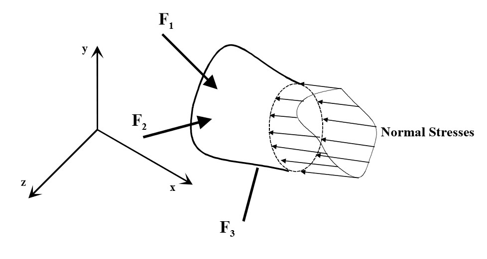
1.1.1 Normal Stress
Normal stress (denoted by or ) is the stress component caused by a force perpendicular to the cross-section that we are analysing. The effect of a normal stress is usually a volume change (however this depends on perspective). Pure volume change only occurs if there is an equal normal stress in all directions acting on a body, otherwise some shape change will occur.
It most likely that we will be calculating the average normal stress over a finite area rather than an infinitesimal area, and hence average stress would calculated from the following formula:
Where is the normal component force acting over the cross sectional area of a body. The value of the average normal stress assumes that is entirely uniform over the, which is usually not the case in practical scenarios.
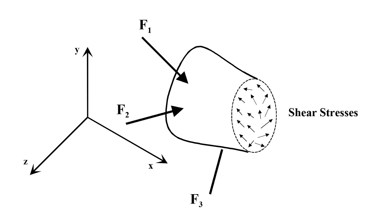
1.1.2 Shear Stress
Shear stress (sometimes denoted as ) is the stress component caused by a shearing force (or couple of forces) acting parallel or tangential to a surface. When working in three dimensions it’s best to break the shear force into two independent components, and . Shear stress has the effect of a shape change, with the body deforming into a completely new shape.
Again we are likely going to be focused on average shear stress which can be calculated using the following formula:
Where is the total tangential force (in one co-ordinate direction) and is the area of contact between the shearing bodies.
1.1.3 3 Dimensional Stresses
In most general cases of 3 dimensions, there may be a maximum of 6 components of stresses, being 3 normal stresses , , , and 3 shear stresses , , . These components together make up the stress tensor, a 3*3 symmetric matrix.
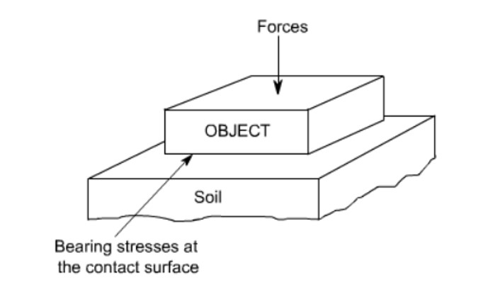
1.1.4 Bearing Stress
Bearing stress is a compressive stress that acts between two bodies when one body is pushed against another. Similar to internal normal stress in that the force is acting perpendicular to the surface area, however the surface area itself is the contact area between the two bodies as in shear stress.
Bearing stress itself is calculated from the following formula:
1.2 Strain
A strain is defined as the ratio of the deformation to the original size of abody (intensity of deformation essentially). There are two types of strains that correspond to our two main stresses:
- Normal strain
- Shear strain Strains are dinmensionless but are often given units of m/m, mm/mm or . In practical engineering strains are much easier to measrue than stress due to the fact that we are measuring phsyical deformations. As a part of this course, definitions are based on infinitesimal displacements and deformations associated with shear are usually neglected.
1.2.1 Average Axial Strain
The average axial strain (or normal strain) is assuming the strain is uniform through the cross-section, which in turn means that the deformation is equal across the body. Average axial strain over a length can be calculated using the following formula:
Where is the change in length and is the original length of the body.
1.2.2 Shear Strain
The shear strain is a measure of the angle of distortion and is usually denoted by

This angle is calculated through simple trigonometry:
1.3 Relationsip between strain and stress
Due to the fact that direct measurement of strain is much easier than measuring stress, through the use of material properties we develop a relationship between stress and strain. This content is covered in Week 3 content
1.3.1
2. Mechanical Properties
2.1 Stress vs Strain Diagrams

A stress-strain diagram shows us the behaviour of a material’s shape deformation, as it moves through elastic to plastic deformation and finally to necking and fracturing. The elastic behaviour of the material is informed by the linear relationship between the stress and strain. The ratio of the this region describes the Elastic Modulus or Young’s Modulus (E):
This equation is also a materially intrinsic version of Hooke’s Law.
2.2 Poisson’s Ratio
The ratio between the width and the depth change of an element undergoing a compressive stress is a useful material property and known as Poisson’s Ratio (v).